When a two port network, typically a microwave amplifier,is terminated in load and source impedances the input and output reflection coefficients are modified. The output reflection coefficient, TOUT is calculated using s parameters, the input termination, ZS and the output termination ZL. In addition the characteristic impedance of the microstrip or transmisson lines is also required.. Signal Processing Group Inc., has developed simple calculators to do this. A calculator for TIN and TOUT are both available on our website and may be accessed from the complementary items menu.
Monthly Archives: March 2016
RF amplifier, HF amplifier, RF amp, low noise amplifier, microwave amplifier, broadband amplifier and amplifier module products from Signal Processing Group Inc.
RF amplifiers, be they just a RF amplifier, a HF amplifier, a RF Amp, a low noise amplifier, a microwave amplifier, a broadband amplifier or RF amplifier modules are incredibly useful items. Currently Signal Processing Group Inc., has designed, developed and is delivering these types of amplifiers. Interested parties can simply, either purchase them from the SPG website or from a online store like Amazon. Please go the RF amplifier page and check out the SPG offerings.

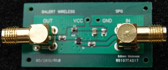
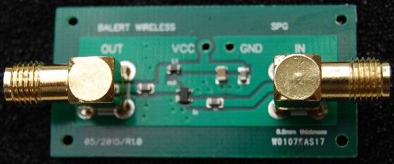
A low noise RF amplifier by Signal Processing Group Inc. Please click on the image to check out other RF amplifiers from SPG
Please note that high volume supply is available with an increased lead time. Please contact us for volume deliveries on spg@signalpro.biz or call 866-487-1119.
In addition,full custom RF amplifier design is available to our customer’s specifications. Please contact us with summary specifications for a budgetary quote at no cost.
Calculator for the characteristic impedance of edge coupled differential microstrip
In an earlier post the differential impedance of edge coupled microstrip was described. A calculator for the differential impedance is also available. The differential impedance is also dependent on the characteristic impedance of the microstrip used . Therefore a calculator was developed to find the characteristic impedance of the microstrip. . All of these resources and tools can be accessed from the Signal Processing Group Inc., website by using the “complementary” link.
Differential impedance of coupled microstrip lines
When two parallel, closely spaced, microstrip lines are used to deliver a differential signal to a load, the differential impedance between them can be calculated using a closed form expression. This impedance is not the characteristic impedance of the individual lines. The differential impedance is modified by the proximity of the two lines to each other. A calculator has been developed by Signal Processing Group Inc., to do this using javascript.
The input to the program is:
1) Characteristic impedance of the lines – Zo
2) The thickness of the PCB – h
3) The spacing of the lines on the PCB—s
It is recommended that when adjusting the dimensions of the lines to get the required differential impedance ( Zdiff) the width of the lines be adjusted, not the spacing.
Another javascript provides a calculator to do this adjustment. This calculator requires the following inputs:
4) εr the dielectric constant of the substrate
5) t, the thickness of copper
6) W, the width of the strip
7) h, the thickness of the substrate.
The javascripts are interactive and these constants can be inserted as it runs. Both the scripts can be accessed from the SPG website by interested users.under the complementary menu i
Here are some design rules for the use of differential microstrip lines.
Design Rule 1 The traces should be of equal length.
Design Rule 2: Route differential traces close together.
Design Rule 3: Differential impedance calculations are necessary with differential signals and traces.
Design Rule 4: The separation between the two traces (of the differential pair) must remain constant over the entire length.
Check out this impedance matching book available from Amazon.
Gallium Arsenide and other III-V technologies
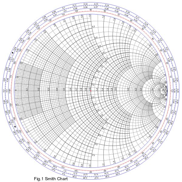
Its wonderful to see the progress made by the III-V technology companies in providing the foundry services and products for really high performance products and MMICs. When I started in GaAs the maximum wafer size for a GaAs wafer was about the size of my thumbnail. Today there are Si-GaAs wafers 12 inches across! Design tools for simulation and characterization have also come a long way. Before these developments we were designing MICs and there were none or very few design tools. We matched the input and out reflection coefficients using tiny gold disks of various radii to achieve the optimum matching. I remember getting 1 Watt out of a GaAs FET. It was unknown during those days. It took a thermal bonder, much sweat ( and tears) and precise bondwire matching and the rest of the work to achieve this. Today I work with ADS and similar tools to seriously reduce risk before layout and post layout of the MMICs. MMIC packages have come a long way too. During the days I was learning MMIC design, no packages were available. The die was mounted directly on the Alumina substrate. Now we can get touchstone files for packages and along with the s – parameters of the device itself, a reasonable match can be done a priori. Devices such as pHEMTs were not available then. They are available now. By the way we used TWT’s to test the devices. These were the test boxes provided by HP to test those high frequencies ( mostly X Band) we were designing in. So with the foundry services, the CAD tools, the package data and test equipment available today, MMIC development is much less of a risk today than it used to be. Good job and kudos to all the companies who have made it possible. By the way the accompanying image of the Smith Chart is a reflection ( no pun intended) of the workhorse tool of those early days of MMIC design. By Ain Rehman, Signal Processing Group Inc.
Microwave amplifier design: Rollet’s K factor.
In 1962 John Rollet published a paper in the IRE called Stability and Power – Gain invariants of Linear two ports. In this he described the K – factor for an amplifier. When designing an amplifier or selecting one from a catalog, check the K factor. If the K – factor is greater than 1, then the amplifier is unconditionally stable, if not then it should be checked for stability. It could be conditionally stable, or in the worst case, unstable. You can access a javascript calculator from the Signal Processing Group Inc,. website to calculate K. Just select the complementary menu item and choose the calculator link,


