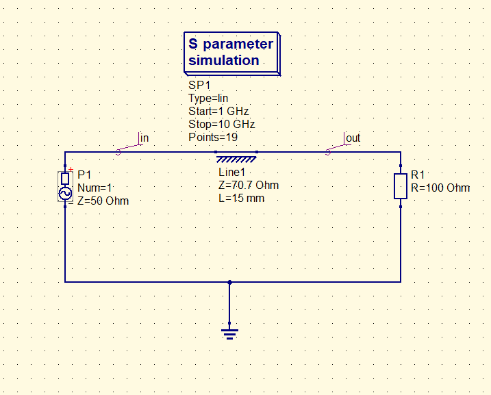
A cascaded transmission line is one of the simplest ways to match impedances. It is simply a quarter wave transmission line with a characteristic impedance given by : Z0 = sqrt(ZS.ZL) where ZS is the source impedance and ZL is the load impedance. A simulation using a public domain simulation CAD tool was performed for s11. The result is shown below:
From the figure the frequency was 5 Ghz. The schematic of this design is shown below:
Note that the impedance of the line is: sqrt(50*100). The length of the line is a quarter wavelength ( 1 wavelength = 60 mm at 5 Ghz).
For more information on impedance matching please refer to the available book : “VSWR and Impedance matching techniques”, available from Amazon,
In addition a forthcoming book that includes many other techniques and scripts is in preparation.
Please visit our website for more information on our offerings and more technical information/articles.
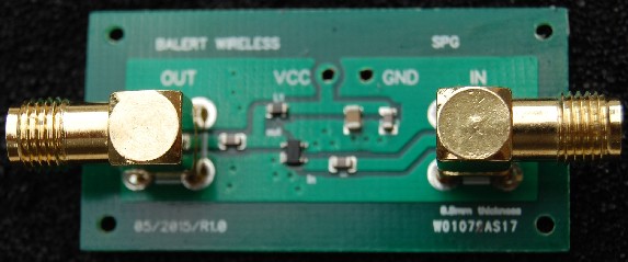
A low noise amplifier module with NF = 1 dB across the 100 Mhz to 3.0 Ghz band with typical 17.7 dB small signal gain over the band.


