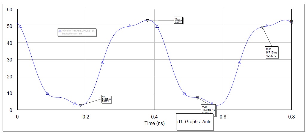
A class F amplifier is highly efficient and uses waveform shaping at the drain of a power device. This shaping takes the form of using ( usually) the second and third harmonic of the waveform to generate a drain to source ( collector to emitter) voltage that is roughly a square wave ( ideally a square wave, but we all know that ideal is a not a word we can use loosely). The drain current is then shaped to be very small when the D/S voltage is high and high when the D/S voltage is low. This causes a non-overlapping condition in operation and ensures a high efficiency. A pre-distortion or pre-conditioning circuit is also required to get the desired linearity. ( This is the subject of a later post). The waveforms below are what we got using Microwave Office as the simulator. The active device was a Cree 40010. It is simply instructive to examine the waveforms in case the reader is starting to design a Class F. The figure below represents the drain source waveform.

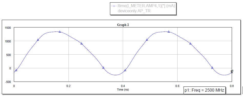
 The figure above is the D.S current in mA.
The figure below is the simulated power gain and PAE.
We hope these will be of help to aspiring designers of Class F amplifiers. Please visit the Signal Processing Group Inc., website for more information and articles of interest.


