A compensation filter for a CIC filter was required. We chose to use the free software tool OCTAVE to help us do this. Here is the sequence of tasks that were done. (Be aware that a compensation filter filter design is not trivial unless you have been doing it for a long while. )
1.0) Design the CIC filter. 2) Measure the droop of the filter . (3) Use the inverse response of the CIC filter to synthesize the compensation filter. (4) Use the frequency response of the inverse filter to generate a frequency – magnitude table. ( Much like a piecewise linear SPICE signal). This table consists of frequency – magnitude pairs for the compensation filter you want. (5) Use this table as the input to the function fir2(n,f,m) in Octave. This function provides the coefficients of the filter you need. However, the trick is to choose the right “n”; It took us a while to get the value of n right for our purposes. You will have to choose yours however you wish. (6) Run fir2 and take the results ( say “b[]”) and generate the impulse response of the filter from it using another OCTAVE function called impz(). The input argument is the “b[]” you just got from fir2. Once you have the impulse response use the freqz function in Octave to simulate the filter you just designed. Once you have the frequency magnitude characteristic of the new filter you can do a multiplot using the plot function from OCTAVE. This allows you to compare the two filters. i.e. the filter you wanted and the filter you designed.
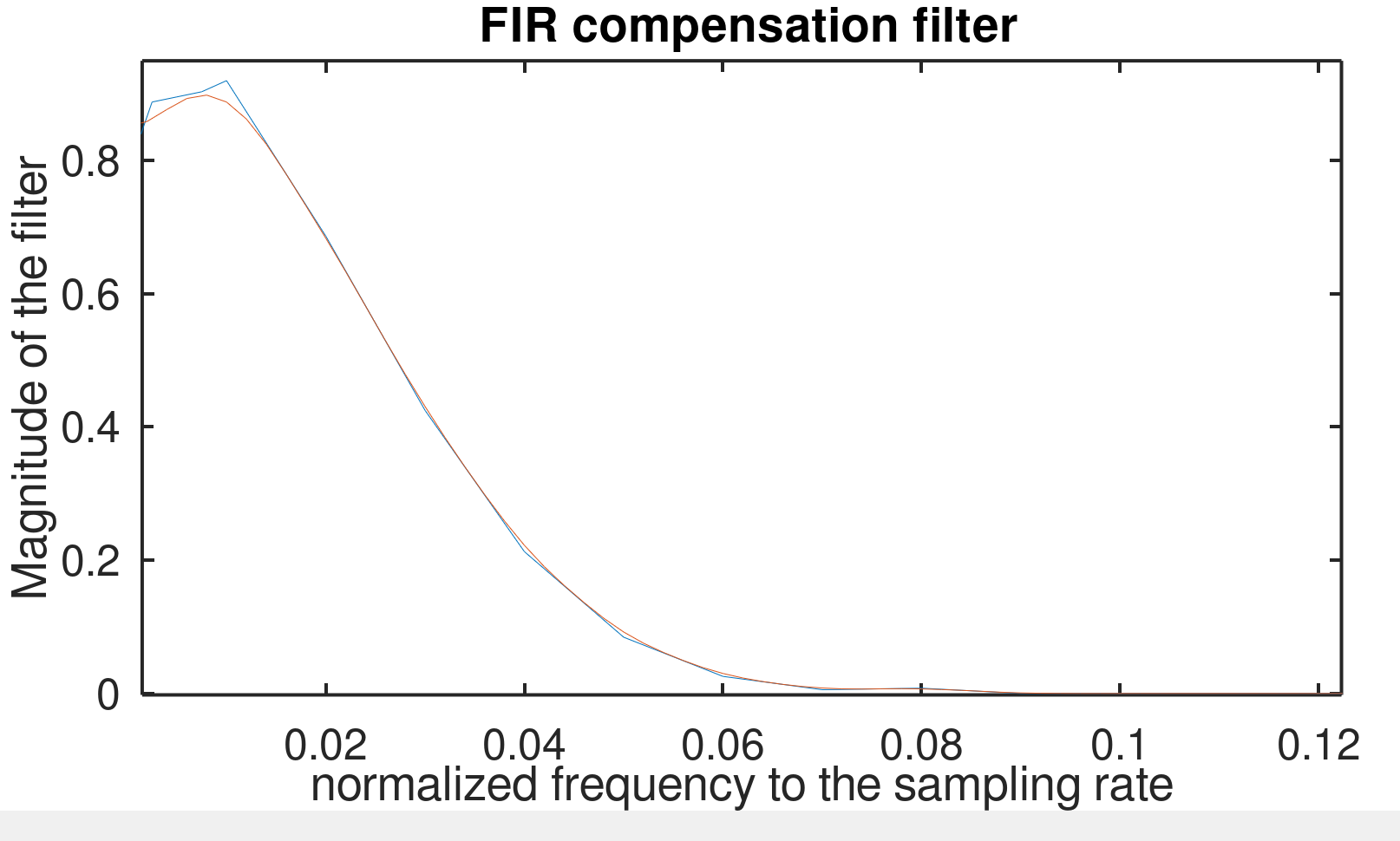
You can make adjustments by using multiple runs of the above sequence until you get the best filter you can get, An example of the multiplot is shown below. The blue line is the original filter and the orange line is the one we got from using the sequence quoted above. Please visit the Signal Processing Group Inc website for more info and contact information.

