3D printing for prototypes

3D design and printing has been gaining momentum recently for use in various applications — from microstructures to houses. Electronic enclosures and other parts are no exception. 3D design and printing is a quick way to make enclosures and fast prototypes using many different types of materials. The image below is a lighthearted print of a dragon. Be that as it may, if you want to print using a 3D printer please contact us for a bid as well. Please visit the SPG website for more information on our capabilities in electronics, ASICs and RF/Microwave modules.

Colpitt’s Oscillator book by Ain Rehman

A new book on the subject of the Colpitt’s Oscillator was just released on Amazon. This is a small book (text wise) but with an extended coverage of the subject for hands on work by engineers and students and other interested readers. It is very economical as far as the text and mathematical derivations go but supported by javascripts and a very extensive list of references that causes the virtual footprint of the book to be fairly massive. Interested readers may pick it up from
Colpitt’s Oscillator: Theory, design, simulation, references: Rehman, Mr Ain: 9798406680810: Amazon.com: Books

Vector Modulator

A vector modulator is a very versatile device that can be used to adjust the amplitude and phase of a RF signal. i.e it combines the functions of phase shift and attenuator. A vector modulator is a key component in 5G networks and can be used as a beamformer. It can be used in generating complex signals such as QPSK and QAM. It is also used in digital predistortion networks for RF power amplifiers. Please visit the Signal Processing Group Inc website for more technical information and articles.

Tf and fT relationship and calculations.

tf and fT are two closely related parameters for a bipolar model. Usually the parameter tf is included in the model and fT can be calculated from it and other parameters. tf is used to model the effect of the excess charge stored in the transistor when it is biased in the forward active region. i.e. the base – emitter junction is forward biased and the base collector junction is at 0 Volts. It is needed to calculate the emitter diffusion capacitance. fT is the transistor’s unity gain bandwidth defined as the frequency where the common emitter, zero load, small signal current gain extrapolates to unity ( Ref:”Modeling the bipolar transistor”. Ian Getreu). CAD programs use many different ways to use tf to convert to fT. However, this blog simply provides a way to get the conversion done to estimate the fT from tf. This provides the engineer a quick way to see what he may be dealing with without a lot of calculator overhead. If he needs a very accurate number he can always use an expensive simulator. This simple conversion is given by: fT(max)= 1/(2*pi*tf). This simple conversion assumes a zero value for the transistor’s internal collector pad to collector pin resistance. This resistance is assumed to be very small so this expression is a good estimate. Another assumption is that this is the maximum or peak value of fT. A calculator based on this expression is available from the Signal Processing Group website for download free of charge. Please visit the SPG website for other items of interest in analog and RFMW design.

Accurate public domain device model for GAN devices from manufacturers.

As more and more designs for RFMW circuits get done, we need a good public domain active device model of GAN devices supported by fabrication vendors and suppliers of GAN devices. This would accelerate and accentuate revenue for both the supplier and the user. In addition to this, this model needs to be implemented in a public domain application program/simulator such as QUCS. The reason is that existing simulators are much too expensive to acquire and use. The simulators like ADS and Microwave office cost an arm and a leg to use. Following on the record of SPICE II it seems that a similar trajectory needs to implemented for a RFMW simulator like QUCS.

Colpitt’s Oscillator frequency estimation calculator

The Colpitt’s oscillator is a useful building block that is simple to build using a very few components. However, it is somewhat difficult to design and simulate. Signal Processing Group has recently released a simple Javascript calculator that provides an estimation of the frequency of the design. However, after this calculator is used the user must still “tweak” the design on the board. Please access the calculator at www.signalpro.biz/calculators/resonant_f.htmh

Hybrid pi model of the bipolar transistor

The hybrid pi model of the bipolar transistor is a popular model used for small signal modeling of the bipolar. A paper released by Signal Processing Group describes the components that constitute the model and presents first order expressions for their calculation. The paper is available for free on the Signal Processing Group website and can be accessed from the “complementary” menu. Please visit. In addition a javascript calculator is planned for release from Signal Processing Group that can be used by a user to make the calculations easier.

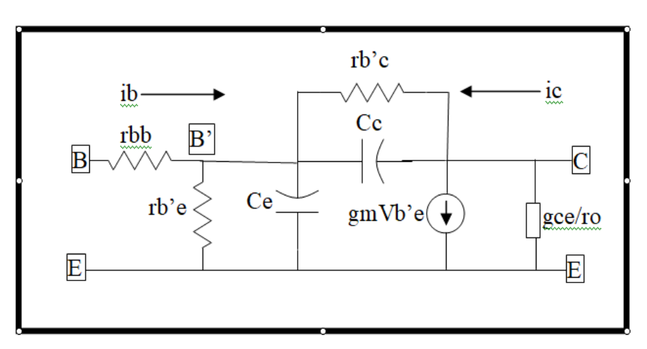
The Hybrid Pi model of Bipolar ( and MOSFET) devices

The hybrid Pi model is a popular model used to analyze small signal performance of active circuits based on bipolar and MOSFET transistor and other devices with appropriate modifications. The following are the descriptions of its component parts:

  1. It has three terminals ( the schematic shows a bipolar model with base, emitter and collector as its terminals. C = collector, B = base and E= emitter.
  • rbb is the base spreading resistance. The resistance between the base contact and the internal base of the transistor.
  • rb’e is the base to emitter resistance.  Represents the base current required to make up for recombination of minority carriers in the base region.
  • Ce is the emitter base diffusion capacitance.
  • Cc and rb’c represents the Early effect which accounts for the finite collector to emitter output resistance.
  • gce/ro represents the output impedance ( conductance) of the device.

This complete model can be simplified as needed for active circuits using these devices.

Colpitt’s oscillator output voltage calculation using ” describing functions”

Colpitt’s oscillator is a popular oscillator circuit which is constructed from an inductor, two capacitors, some resistors, and an active device such as a bipolar or a MOSFET, and generally some trial and error !!! Of particular difficulty is the calculation a priori, of the output voltage of the oscillator. However, a technique using the describing function of a bipolar ( or MOSFET or JFET, IGFET etc) makes it possible to calculate the output voltage to a close estimate. ( Perhaps some optimizing needs to be done). For the uninitiated here is a simple definition of a describing function. Assume you have a non linear device which you would need to analyze, using linear tools. How would you do it? In the time domain it is definitely non linear but if you switch to the frequency domain linear analysis tools can be applied. How? Hit the non linear system with a sinusoid of a particular amplitude and frequency. Since the system is non linear it will generate, at its output, a number of sinusoids. Lets pick the output sinusoid that matches our input frequency and all its associated characteristics ( phase etc). This becomes a describing function. Ignore the rest of the outputs. Then linear analysis tools can be applied to this describing function and results obtained. Please visit our website for more technical info and other information.